TM Trussの実績
Furudono Town People’s Gymnasium Yabusame Arena
-
- [Products & Services]
- TM Truss
-
- [Purpose / Application]
-
- [completion of construction]
- 2018
-
- [Location]
- Fukushima
Reliable structural system backed by extensive experience.
High-quality, high-precision structures are realized through a fully systematized management system from design, production, to construction. Compact packaging allows for easy delivery even to narrow lots, and short-term construction is possible without the use of large, heavy machinery. The high earthquake resistance has also been proven, with zero damage from collapse caused by the two earthquakes of the Great East Japan Earthquake and Tsunami, enabling the creation of highly safe facilities.
*For sale only in the Japanese market
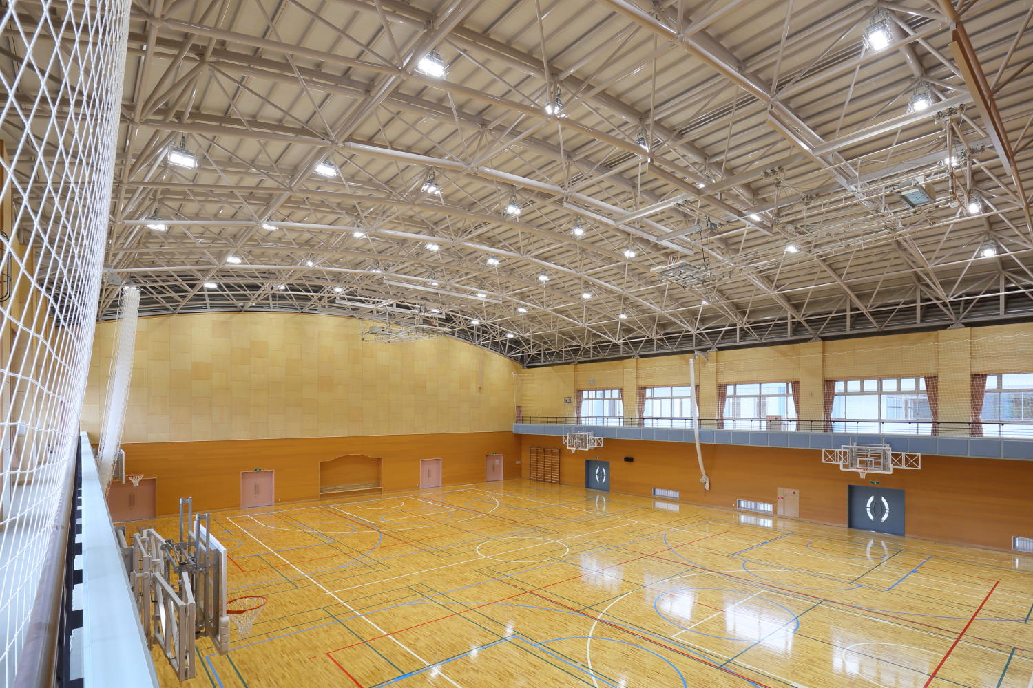
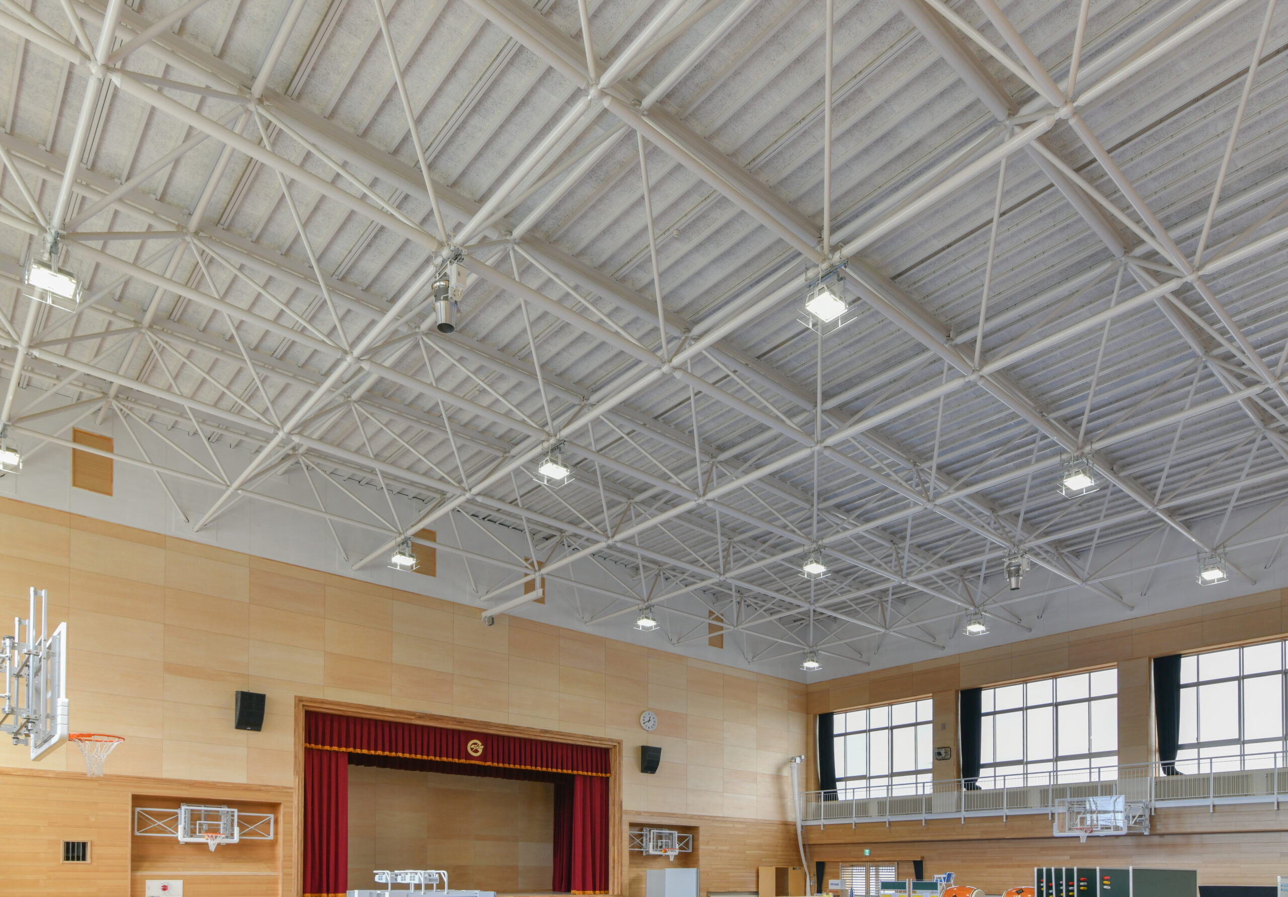
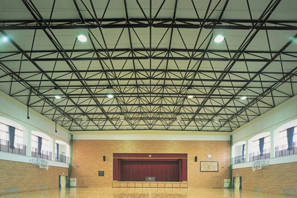
TM trusses are used in various locations throughout Japan.
TM trusses are used in more than 1,000 gymnasiums, large spaces, and in every other situation where people come and go. Our extensive track record is proof of our reliability.
It is also safe during earthquakes.
TM trusses can form a roof structure with about half the weight of ordinary steel frames, which reduces the load on columns and other parts of the structure and increases seismic safety. Even in the Great East Japan Earthquake of March 11, 2011, there was no damage from collapse due to earthquake. TM trusses also protect the safety of users in areas where there is a lot of human traffic, such as aisles and canopies.
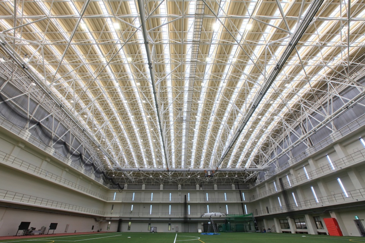
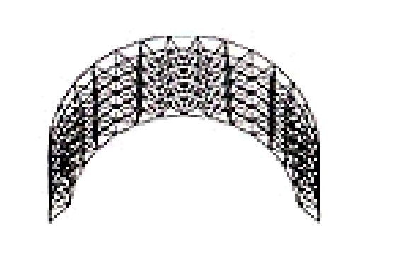
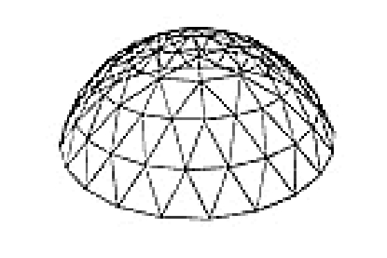
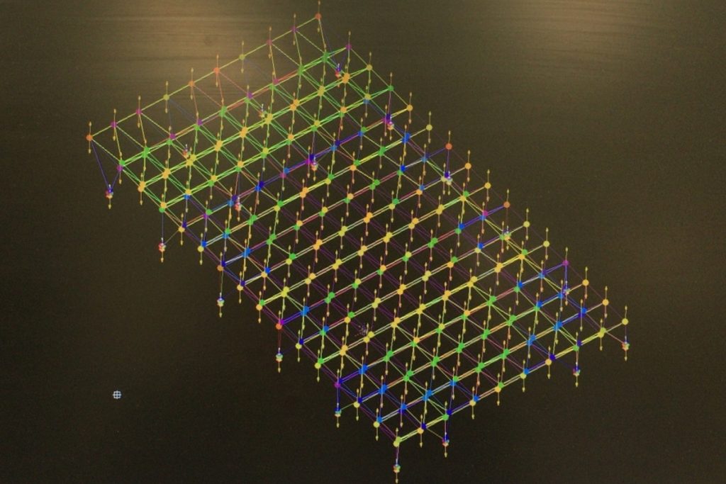
We can create a form (structure) that matches the image of the facility.
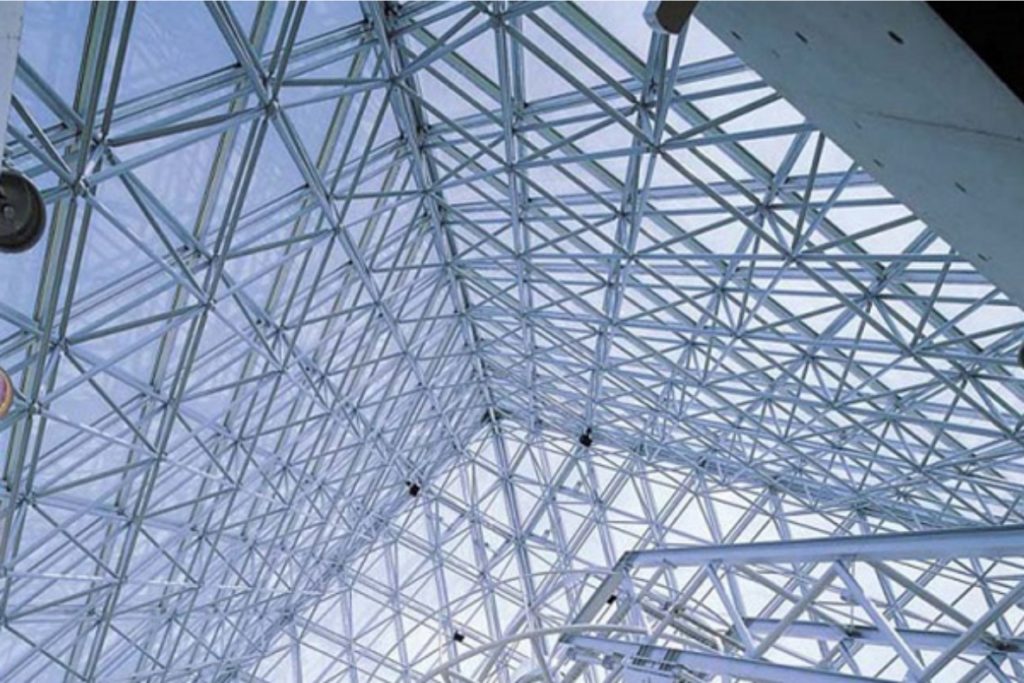
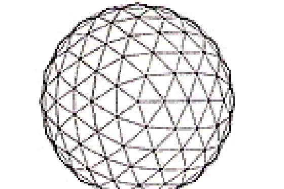
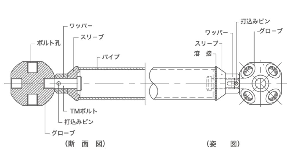
The TM truss consists of a series of pipes and globes. The length and angle of the members can be set arbitrarily, enabling structural design in accordance with facility plans.
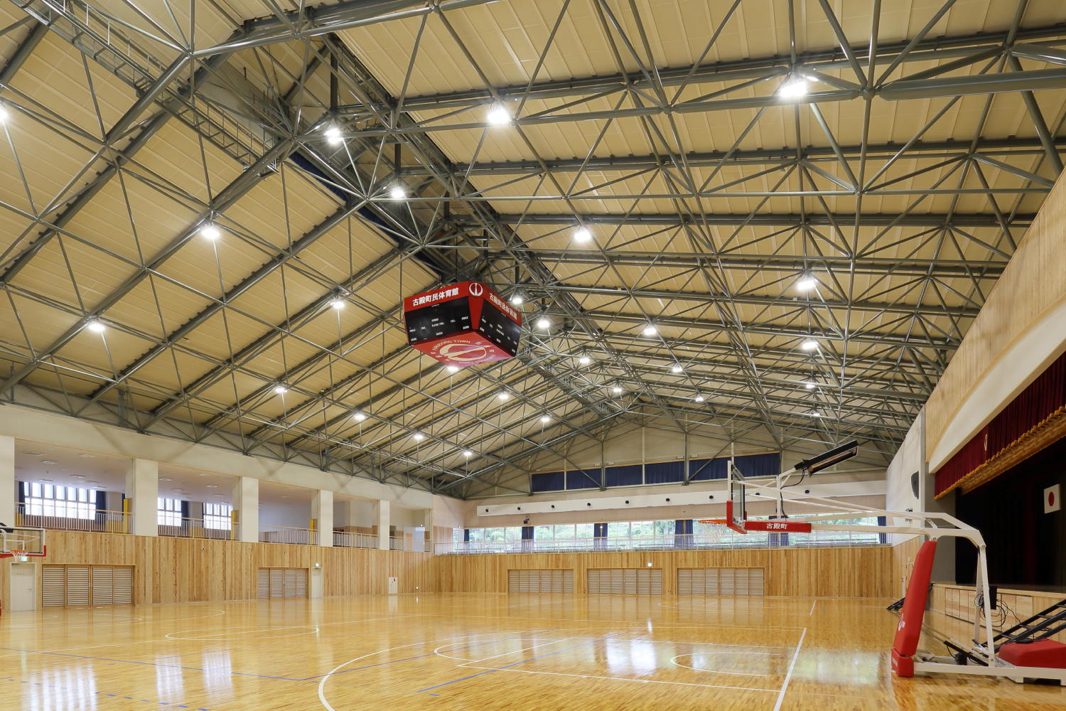
Fewer columns are needed.
The TM truss structure, which is based on rational stress relationships, can provide a roof structure with a small number of columns even in large spans. This minimizes the number of columns that tend to interfere with passageways, creating a light and open space.
Construction plans can be made in accordance with the property.
The systematized construction method allows for easy transportation, assembly, and management, resulting in high workability and shortened construction time. The components are lightweight single materials, which can be carried in even to sites with narrow roads, and can be worked by hand, minimizing the use of heavy machinery.
The seismic energy of an earthquake is proportional to the weight of the building.
The weight of the roof structure formed by TM trusses is about half that of a standard steel frame. This reduces the burden on columns and other parts of the structure and increases seismic safety. It is especially suitable for corridors and canopies where there is a lot of pedestrian traffic and safety is a major concern.
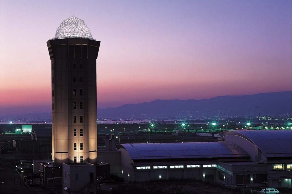
Lighting enhances the beauty of the structure and makes it float beautifully in the night space.
Stenless trusses, in particular, shine more spectacularly. It can also be used not only as a roof, but also as an elegant lighting and art object.
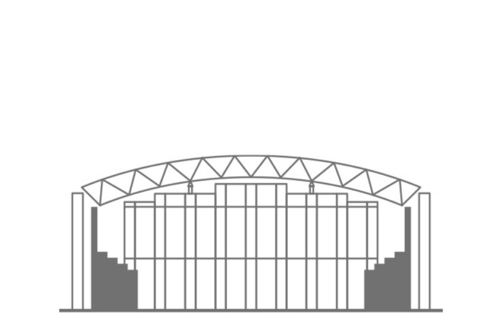
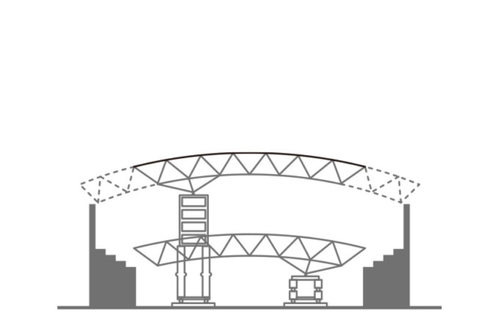
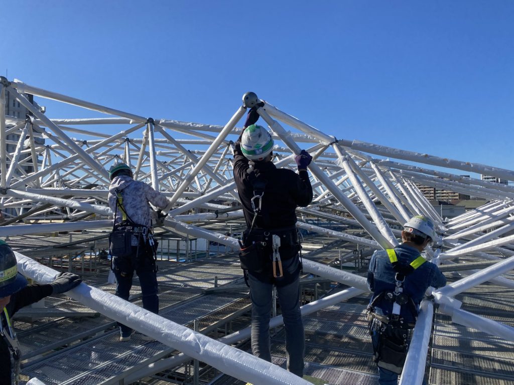
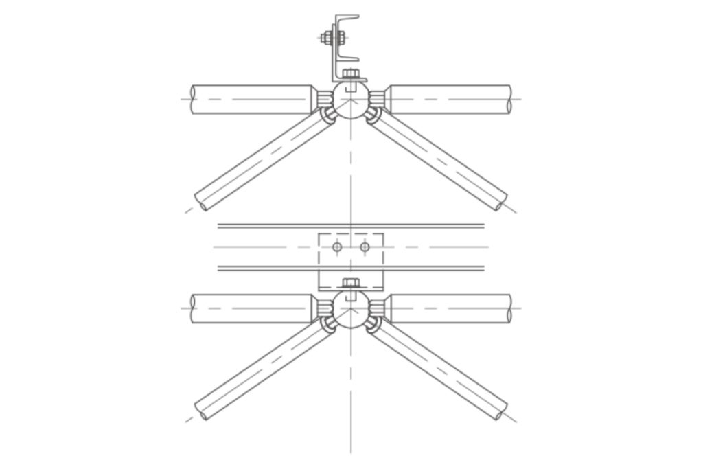
Pipes, globes, and other components are placed on scaffolds and hand-assembled. This is the most orthodox construction method.
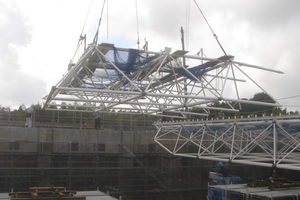
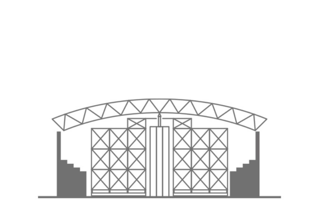
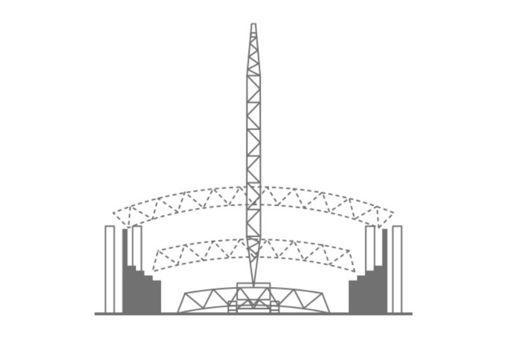
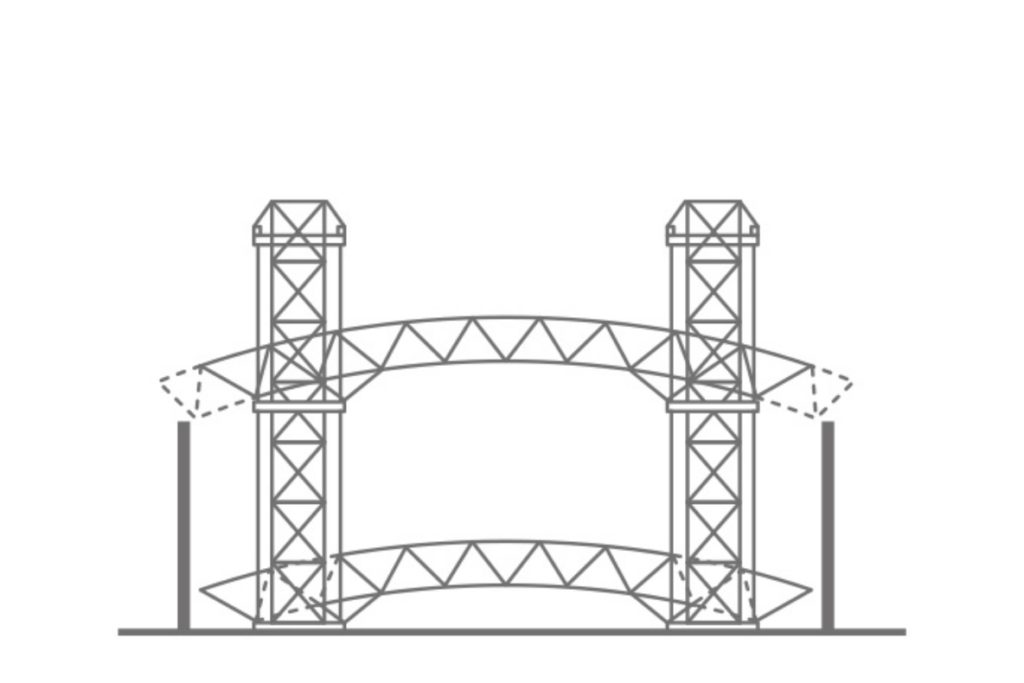
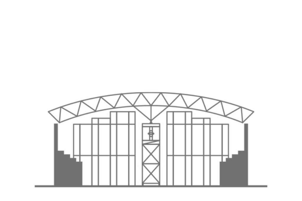
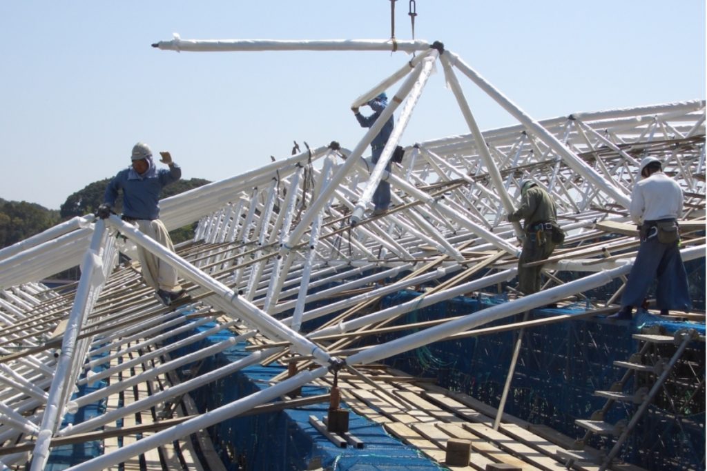
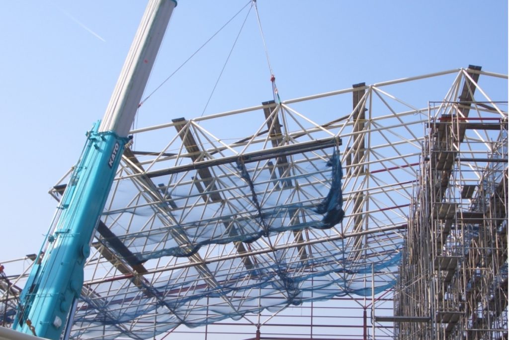
The glove and several pipes are assembled in advance in the yard into an “octopus leg” and then weighed and joined together by heavy equipment. This method is useful for projects with large beam sizes.
The glove and several pipes are assembled in advance in the yard into an “octopus leg” and then weighed and joined together by heavy equipment. This method is useful for projects with large beam sizes.
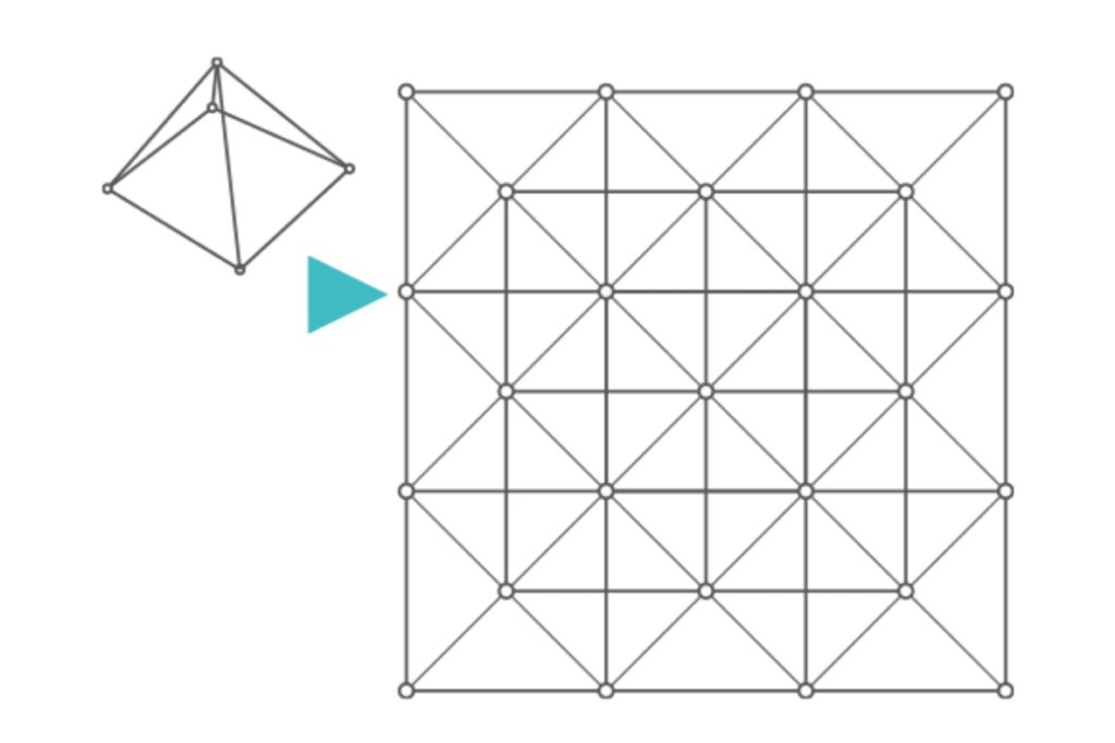
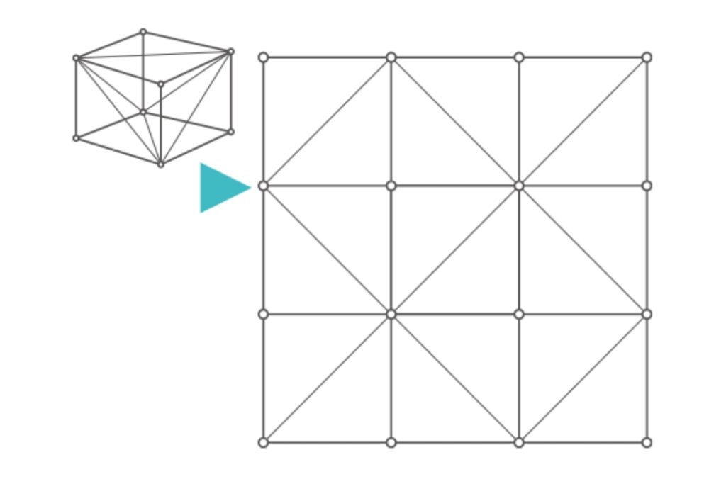
How to assemble a lightweight structural system
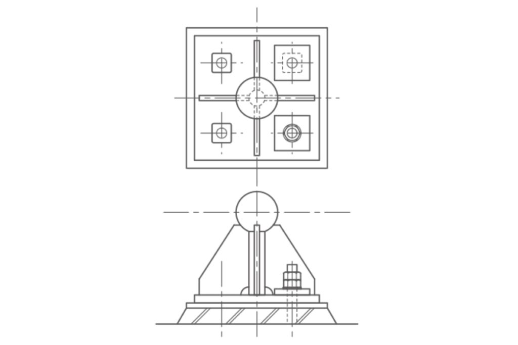
Components of lightweight structural systems
From planning to construction of lightweight structural systems
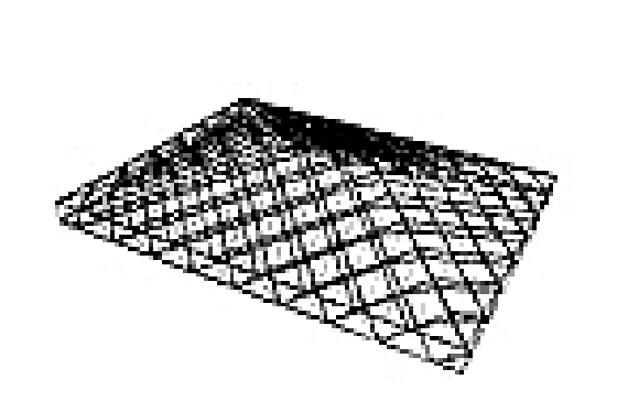
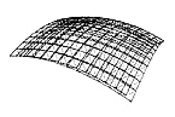
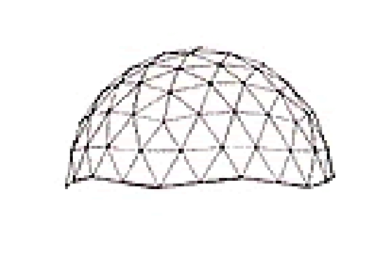
There are three basic forms of assembly: triangular pyramid, square pyramid, and rectangular pyramid.


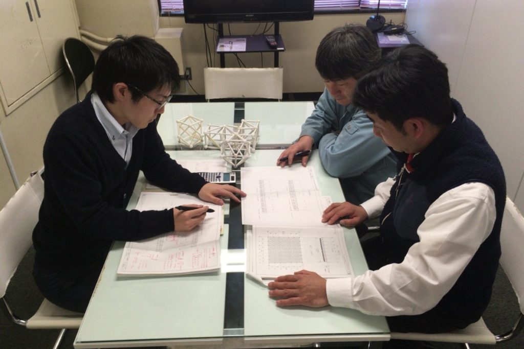
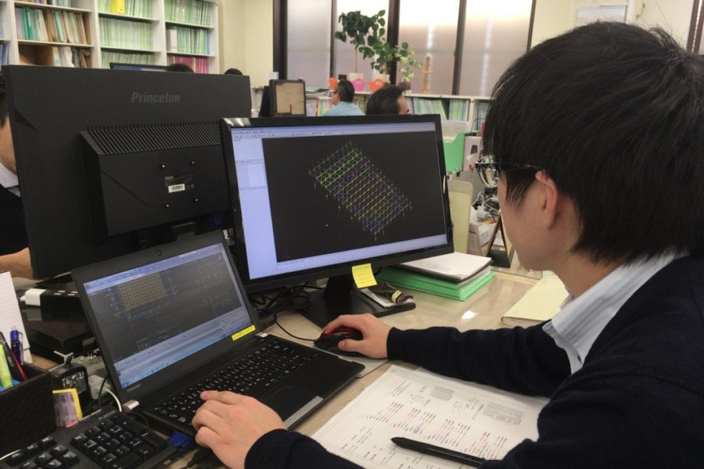
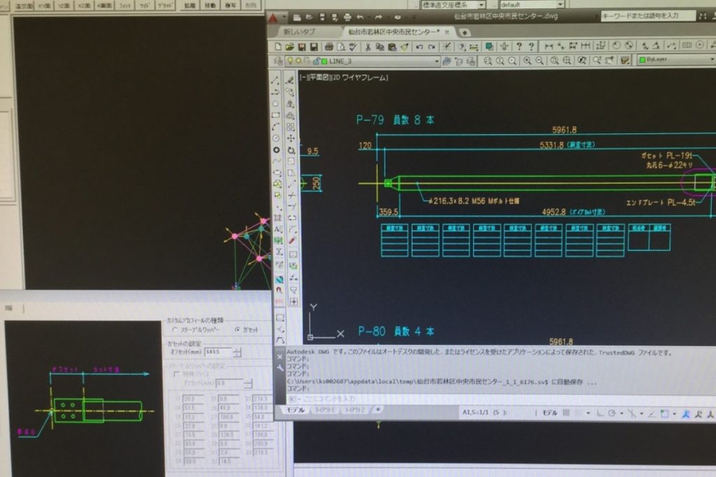
We calculate stresses and select materials using a dedicated computer program. Please feel free to consult with us about your design plans.
| Name of parts used | Name of parts used | Applicable Standards | name |
|---|---|---|---|
| glove (esp. sports) | 5T | JIS G 3106 | Rolled steel for welded structure SM 490 A equivalent |
| JIS G 3136 | Rolled steel for welded structure SM 490 B equivalent | ||
| JIS G 4051 | Carbon steel for machine structural purposes S 45 C | ||
| 9T | JIS G 4105 | Chromium molybdenum steel SCM 435, SCM 440 | |
| JIS G 4052 | SCM 435H, SCM 440H | ||
| 6T | JIS G 4105 | Chromium molybdenum steel SCM 435, SCM 440 | |
| JIS G 4052 | SCM 435H, SCM 440H | ||
| pipe | – | JIS G 3444 | Carbon steel for general structural purposes Kan SKT 400 |
| JIS G 3475 | Carbon Steel Kan for Building Construction TKN 400W, STKN 400B | ||
| sleeve | – | JIS G 3101 | Rolled steel for general structural purposes SS 400 |
| bolt | 5T | JIS G 4051 | Carbon steel for machine structural purposes S 45 C |
| 9T | JIS G 4105 | Chromium molybdenum steel SCM 435, SCM 435H | |
| Equivalent to 9T | JIS G 4052 | Nickel Chromium Molybdenum Steel SNCM 439 | |
| JIS G 4103 | |||
| Whopper. | 7T | JIS G 4051 | Carbon steel for machine structural purposes S 45 C |
| hammer pin | – | JIS G 4314 | SUS 304 WPB |
| JIS G 4105 | SCM 435 | ||
| pin screw | – | JIS G 4105 | SCM 435 |
| Globe size (Do/D1) | |||
|---|---|---|---|
| 50/46 | 85/78 | 110/103 | 130/120 |
| 150/136 | 180/160 | 200/182 | 220/192 |
| 260/240 | 300/270 | 410/380 | |
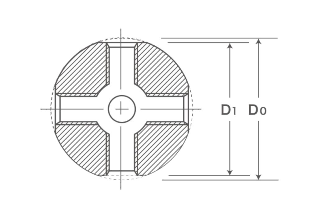
Once the bolt diameter is determined, the size of the glove is determined by the required insertion length.
| number | Bolt Wapper (right)/ Pipe (bottom) | M12 SW19 | M16 SW24 | M20 SW30 | M24 SW38 | M27 SW41 | M30 SW46 | M36 SW55 | M42 SW70 | M48 SW80 | M56 SW90 | M60 SW95 | M68 SW110 | M76 SW120 |
|---|---|---|---|---|---|---|---|---|---|---|---|---|---|---|
| 1 | 50/46mm dia. | ✓ | – | – | – | – | – | – | – | – | – | – | – | – |
| 2 | 85/78mm dia. | ✓ | ✓ | ✓ | – | – | – | – | – | – | – | – | – | – |
| 3 | 110/103 mm dia. | ✓ | ✓ | ✓ | ✓ | – | – | – | – | – | – | – | – | – |
| 4 | 130/120mm dia. | ✓ | ✓ | ✓ | ✓ | ✓ | ✓ | – | – | – | – | – | – | – |
| 5 | 150/136mm dia. | ✓ | ✓ | ✓ | ✓ | ✓ | ✓ | ✓ | – | – | – | – | – | – |
| 6 | φ180/160 | ✓ | ✓ | ✓ | ✓ | ✓ | ✓ | ✓ | ✓ | – | – | – | – | – |
| 7 | 200/182mm dia. | ✓ | ✓ | ✓ | ✓ | ✓ | ✓ | ✓ | ✓ | – | – | – | – | – |
| 8 | Diameter 220/192 | ✓ | ✓ | ✓ | ✓ | ✓ | ✓ | ✓ | ✓ | ✓ | – | – | – | – |
| 9 | 260/240mm dia. | ✓ | ✓ | ✓ | ✓ | ✓ | ✓ | ✓ | ✓ | ✓ | ✓ | – | – | – |
| 10 | 300/270mm dia. | ✓ | ✓ | ✓ | ✓ | ✓ | ✓ | ✓ | ✓ | ✓ | ✓ | ✓ | ✓ | ✓ |
| 11 | 410/380mm dia. | ✓ | ✓ | ✓ | ✓ | ✓ | ✓ | ✓ | ✓ | ✓ | ✓ | ✓ | ✓ | ✓ |
Combine bolts/wappers and pipes according to stress, deformation, etc.
| number | Bolt Wapper (right)/ Pipe (bottom) | M12 SW19 | M16 SW24 | M20 SW30 | M24 SW38 | M27 SW41 | M30 SW46 | M36 SW55 | M42 SW70 | M48 SW80 | M56 SW90 | M60 SW95 | M68 SW110 | M76 SW120 |
|---|---|---|---|---|---|---|---|---|---|---|---|---|---|---|
| 1 | Φ34.0 × t2.3 | ✓ | – | – | – | – | – | – | – | – | – | – | – | – |
| 2 | Φ42.7 × t2.3 | ✓ | ✓ | – | – | – | – | – | – | – | – | – | – | – |
| 3 | Φ48.6 × t2.3 | – | ✓ | ✓ | – | – | – | – | – | – | – | – | – | – |
| 4 | Φ48.6 × t3.2 | – | ✓ | ✓ | – | – | – | – | – | – | – | – | – | – |
| 5 | Φ60.5 × t2.3 | – | ✓ | ✓ | – | – | – | – | – | – | – | – | – | – |
| 6 | Φ60.5 × t3.2 | – | ✓ | ✓ | ✓ | – | – | – | – | – | – | – | – | – |
| 7 | Φ76.3 × t2.8 | – | – | ✓ | ✓ | – | – | – | – | – | – | – | – | – |
| 8 | Φ76.3 × t3.2 | – | – | ✓ | ✓ | – | – | – | – | – | – | – | – | – |
| 9 | Φ76.3 × t4.2 | – | – | ✓ | ✓ | ✓ | – | – | – | – | – | – | – | – |
| 10 | Φ89.1 × t3.2 | – | – | ✓ | ✓ | ✓ | – | – | – | – | – | – | – | – |
| 11 | Φ89.1 × t4.2 | – | – | ✓ | ✓ | ✓ | – | – | – | – | – | – | – | – |
| 12 | Φ101.6 × t3.2 | – | – | – | ✓ | ✓ | – | – | – | – | – | – | – | – |
| 13 | Φ101.6 × t4.2 | – | – | – | ✓ | ✓ | ✓ | – | – | – | – | – | – | – |
| 14 | Φ114.3 × t3.5 | – | – | – | ✓ | ✓ | ✓ | ✓ | – | – | – | – | – | – |
| 15 | Φ114.3 × t4.5 | – | – | – | ✓ | ✓ | ✓ | ✓ | – | – | – | – | – | – |
| 16 | Φ114.3 × t6.0 | – | – | – | ✓ | ✓ | ✓ | ✓ | – | – | – | – | – | – |
| 17 | Φ139.8 × t3.5 | – | – | – | ✓ | ✓ | ✓ | ✓ | – | – | – | – | – | – |
| 18 | Φ139.8 × t4.5 | – | – | – | ✓ | ✓ | ✓ | ✓ | – | – | – | – | – | – |
| 19 | Φ165.2 × t4.5 | – | – | – | – | – | ✓ | ✓ | ✓ | – | – | – | – | – |
| 20 | Φ165.2 × t5.0 | – | – | – | – | – | – | ✓ | ✓ | – | – | – | – | – |
| 21 | Φ190.7 × t5.3 | – | – | – | – | – | – | ✓ | ✓ | ✓ | – | – | – | – |
| 22 | Φ216.3 × t4.5 | – | – | – | – | – | – | – | ✓ | ✓ | – | – | – | – |
| 23 | Φ216.3 × t5.8 | – | – | – | – | – | – | – | ✓ | ✓ | ✓ | ✓ | – | – |
| 24 | Φ216.3 × t8.2 | – | – | – | – | – | – | – | ✓ | ✓ | ✓ | ✓ | – | – |
| 25 | Φ267.4 × t6.0 | – | – | – | – | – | – | – | ✓ | ✓ | ✓ | ✓ | ✓ | – |
| 26 | Φ267.4 × t6.6 | – | – | – | – | – | – | – | ✓ | ✓ | ✓ | ✓ | ✓ | – |
| 27 | Φ267.4 × t9.3 | – | – | – | – | – | – | – | ✓ | ✓ | ✓ | ✓ | ✓ | – |
| 28 | Φ318.5 × t6.0 | – | – | – | – | – | – | – | – | ✓ | ✓ | ✓ | ✓ | ✓ |
| 29 | Φ318.5 × t6.9 | – | – | – | – | – | – | – | – | ✓ | ✓ | ✓ | ✓ | ✓ |
| 30 | Φ318.5 × t10.3 | – | – | – | – | – | – | – | – | ✓ | ✓ | ✓ | ✓ | ✓ |
As a rule, loads are applied to nodes (globes) so that only axial stresses act on the member.
By adopting an integrated computer management system, CIM (Computer Integrated Manufacturing), from design to production and construction, we have achieved lower costs, shorter delivery times, and higher quality.

Work based on the truss assembly implementation flow for each construction method